
DESIGN FEATURES:
Design Specifications :
Etisalat Specification MS 114-B
British Standard BS EN 124 1994
Material .
Ductile Iron to ISO 1083, Grade 500-7.
DESIGN FEATURES:
Design Specifications :
Etisalat Specification MS 114-B
British Standard BS EN 124 1994
Material .
Ductile Iron to ISO 1083, Grade 500-7.
DESIGN FEATURES:
Design Specifications :
Etisalat Specification MS 114-B
British Standard BS EN 124 1994
Material .
Ductile Iron to ISO 1083, Grade 500-7.
DESIGN FEATURES:
Design Specifications :
Etisalat Specification MS 114-B
British Standard BS EN 124 1994
Material .
Ductile Iron to ISO 1083, Grade 500-7.
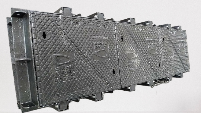
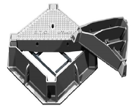
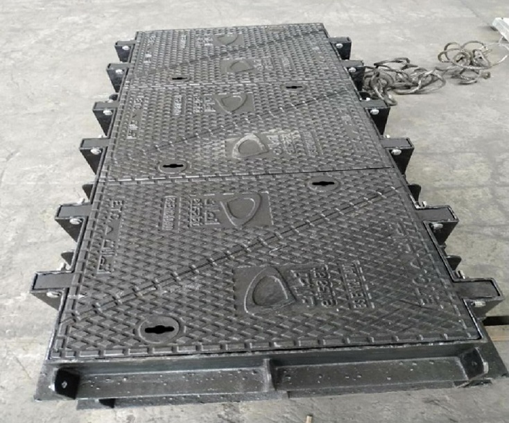
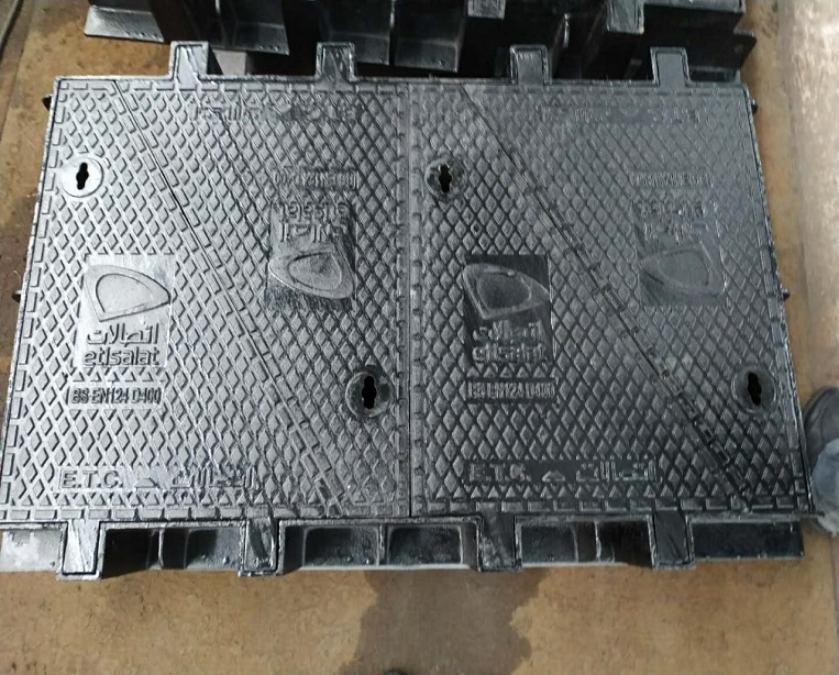
The Access Covers and Frames described herein were designed to satisfy Etisalat requirements, as outlined in their Tender Specifications MS 113-C and MS 114-B, and comply with British Standard BS EN 124. In designing these units especial attention was given to: configuration and functionality; the efficient use of material in meeting structural demands; and, ease of manufacture, to ensure a long service life, strength and stability and quality reliability in manufacture. Units have demonstrated satisfactory service for some ten years.
Quality configuration design was achieved through the combined use of solids modelling software and finite element stress analysis software and was demonstrated by thorough prototype testing. Covers and frames were rigorously designed to withstand the anticipated vehicle loadings and are optimised for minimum weight. The design ‘breakingload’ for Class D400 covers was set at 480 kN. Quality control tests, on covers currently being produced, show covers typically break at between 470 to 510 kN.
Castings will continue to be manufactured under a quality control system meeting the requirements specified in BS EN 124 (see ‘Quality Control Procedures’). And routine load tests, in the manner prescribed by BS EN 124, will continue to be conducted during production.
Accessaries are detailed in the data sheets that follow and, generally, all meet Etisalat specifications. Any departures are noted in the ‘Schedules of Compliance’. The most significant departure relates to the design of Manhole Step No. 1, where two strengthening ribs have been added. Steps of this design have been in service for seven years. The rationale for departing from the Etisalat Specification MS 102-B are discussed below:
Manhole steps are a critical safety item. They are subjected to occasional impact loads (operatives jumping onto steps or slipping from one step to another) and are located in a corrosive environment. A 100 kg person suddenly transferring their weight to the corner of a step would generate a 200 kg dynamic load on the step, which is effectively resisted by only one leg of the step. The highest stress in this leg occurs at the wall and because the concrete embedment in contact with this leg deforms in this area as a result of interaction with this leg the highest stress in the leg actually occurs at a point in the leg within the concrete. Thus, the ruling section for load resistance is not the stronger ribbed section of the leg but the somewhat weaker narrow rectangular section in the concrete (the reason for having a rectangular section is to allow the step to be inserted between brick courses). Coupled with this, the ruling section is likely to be subject to crevice corrosion at the point where it enters the concrete.
The design for Manhole Step No. 1, shown in the data sheets or in Drawing No. 011220, was arrived at through due consideration of the above. An additional rib has been added to increase the strength of the ruling section and to reduce susceptibility to failure through crevice corrosion. Material specified is Ductile Iron Grade 420-12 rather than Malleable Iron Grade B35-12. Ductile Iron is a superior material to Malleable Iron and has largely replaced it. Unlike Ductile Iron, Malleable Iron components must be heat treated after casting to obtain the desired properties, which increases the production costs over that for Ductile Iron.
A load of 6 kN, applied at the centre of the step with the legs clamped, in the manner prescribed in British Standard BS1247 Part 1, is specified for routine testing of production units.
A generous tread pattern, 3 mm high, is provided for positive grip. Step corners have been rounded, generously, to reduce the potential for impact injuries.
| Type | Clear Opening(MM) | EN124 CLASS | Designation |
|---|---|---|---|
| Carriageway 1 | 590 X 590 | D 400 | CW1ST-D/A |
| Carriageway 2 | 1224 X 700 | D 400 | CW1ST-D/A |
| Carriageway 3 | 1835 X 700 | D 400 | CW1ST-D/A |
| Carriageway 4 | 912 X 452 | D 400 | CW1ST-D/A |
| References | BS EN 124 Class | No. of Covers | Clear Opening(1)(mm x mm ) | Overall Frame ( mm x mm) | Frame Depth (mm) | Insertion Depth mm |
|---|---|---|---|---|---|---|
| CW1ST-D/A | D 400 | 2 | 590 x 590 | 744 x 744 | 160 | 75 |
| CW2ST-D/A | D 400 | 4 | 1224 x 700 | 1373 x 850 | 160 | 71 |
| CW3ST-D/A | D 400 | 6 | 1835 x 700 | 1984 x 850 | 160 | 71 |
| CW4ST-B/A | B 125 Test load 150 kN | 1 | 912 x 452 | 1105 x 645 | 96 | 37 |
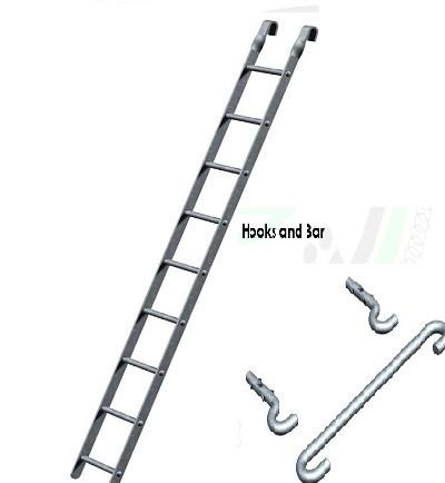
DESIGN FEATURES:
Material:
Mild Steel
Protective Finish :
Hot dipped galvanised in accordence wwith BS729
Design specification:
Ladders,Hooks and Bar comply with Etisalat specification MS109.
Standard Lengths
2150,
2300,
2450,
2600,
2750,
3000,
3250,
3500,
3750.
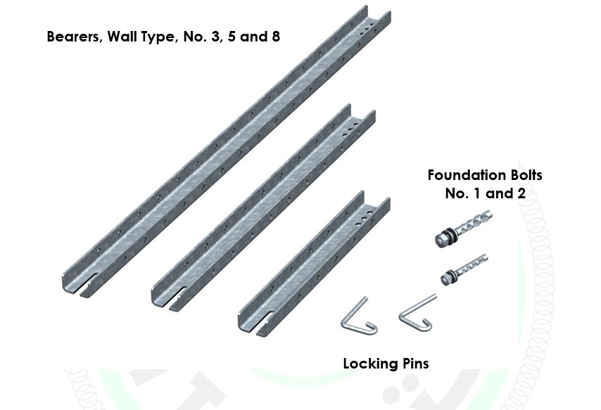
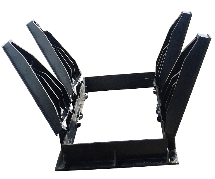
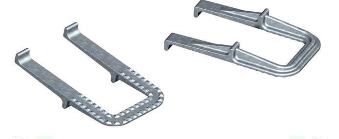
DESIGN FEATURES:
Material:
Bearers: Mild Steel Pressed Channel
Bolts: Mild Steel
Pins: High Tensile Steel Rod
Protective Finish :
All items - Hot dipped galvanised in accordance with BS 729.
Design specification:
Items comply with the following Etisalat Specifications:
Bearers: MS 105 Bolts: MS 108
Pins: MS 101
Standard Lengths
Bearers: 178, 279, 508, 813, 1270, 1574 & 1879
Bolts: 127 (1/2 in. Dia) and 150 (5/8 in. Dia
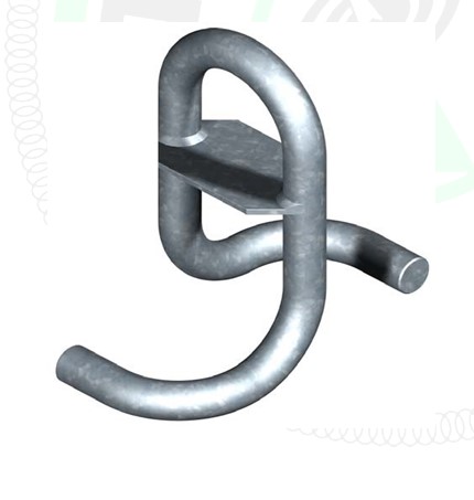
DESIGN FEATURES:
Material:
Mild Steel Bar, normalised at 650 degree C after forming.
Protective Finish :
Hot dipped galvanised in accordence wwith BS729
Design specification:
Etisalat Specification MS 103
DESIGN FEATURES:
Material:
Ductile Iron to BS 2789, Grade 420-12
Protective Finish :
All items - Hot dipped galvanised in accordance with BS 729.
Strength :
Design and test load 6kn
Design specification:
Etisalat Specification MS 102-B
British Standard BS 1247 Part 1